Pages

Subscribe:

Ads 468x60px

Showing posts with label Infrastructure. Show all posts

Friday, February 3, 2012

Mitsubishi Electric Announces New Ultra-High-Speed Elevator Technologies

Engineerblogger
Feb 3, 2012

Shanghai Tower will represent China's dynamic 'future

Mitsubishi Electric Corporation announced today its new suite of technologies that enable ultra-high-speed elevators to travel faster than 1,000 meters per minute, or 60 kph, with enhanced efficiency, comfort and safety. The technologies will be incorporated in the world's fastest elevators, including those developed by Mitsubishi Electric for the 632-meter Shanghai Tower under construction in Shanghai, China.

In response to the increasing height of high-rise buildings amid continuing urban population growth, the role of elevators is gaining even greater importance. In response, Mitsubishi Electric is developing advanced solutions incorporating technologies and equipment for enhanced drive and controllability, safety, super high-rise cable mechanics and passenger comfort. The company's new suite of ultra-high-speed elevator technologies includes the following advancements:

1.  Drive and Controllability
  • The traction motor incorporates a permanent magnetic motor for energy-efficient, low-noise, low-vibration operation.
  • A single motor has two grouped three-phase winding coils and parallel drive systems controlled by separate control panels. Each motor has a built-in converter to regenerate electricity, lowering power consumption by more than 30 percent.
  • Brakes composed of two units with a hydraulic driven clamp-type disk brake achieve stable braking.
 
2.  Safety

  • Safety gears, which activate the brakes by grasping the guide rails in emergencies if cables become transected, comprise two stages to manage increased kinetic energy due to ultra-high speeds.
  • Fine ceramic is used for the safety gear shoe to realize high resistance to heat, abrasion and shock. Braking is extra-stable even if high frictional heat is generated when the safety gear is activated.
  • The hydraulic oil buffer (shock absorber) at the bottom of the elevator shaft has an advanced plunger comprising three stages for exceptional shock absorption within a shortened frame.
  • Newly developed governor monitors elevator speed stably even with heavy loads placed by ropes traveling at high speeds over long distances.

3.  Super high-rise cable mechanics

  • A steel core with a wider diameter provides high intensity, allowing traveling cables to be lightened by using lightweight sheath material and operated by a highly efficient electric power carrier system.
  • Mitsubishi Electric's new "sfleX-rope" comprising bundles of high-intensity steel wire strands, each covered with plastic, offers higher intensity than conventional rope for safe operation despite the greater weight of longer ropes. Each wire has a higher density and wider cross-sectional area than conventional rope, which helps to reduce rope stretching caused when passengers step onto the elevator.


4.  Ride comfort
  •   A new active roller guide, which reduces vibration from the guide rails and wind, enhances passenger comfort even at ultra-high speeds.
  •   The inside of the car is extra-quiet thanks to a streamlined aerodynamic car cover and a high sound insulation cage.
  • Air pressure control helps to minimize rapid changes in atmospheric pressure for reduced ear discomfort.

Just like cars, going that fast also leads to the question of safety – rest assured that Mitsubishi will deliver enhanced efficiency, comfort and safety as thousands of people traverse through these elevators each day. Fine ceramic is the material of choice for the safety gear shoe as it has a high resistance to heat, abrasion and shock. Never mind if high frictional heat is generated, braking remains extremely stable.

Source: Mitsubishi Electric Corporation

Thursday, January 12, 2012

Millennium Project: The Falkirk Wheel

Engineerblogger
Jan 12, 2012


As the Falkirk Wheel approaches its 10th anniversary, its owners couldn't be more delighted in how the one-of-a-kind boat lift has transformed Scotland's once-forgotten and neglected canal system into a thriving recreational and tourist attraction. The 35-m-high, 1,500-tonne structure, internationally recognized as an engineering marvel, reconnects the Forth & Clyde Canal and the Union Canal, a vertical drop of 18 m, and provides water transport between Edinburgh and Glasgow.

Conceived in the 1990s as part of the United Kingdom's Millennium Project, its owners, British Waterways Scotland, were seeking a novel, landmark design to take an Industrial Revolution-era project into the new century. The two canals had been connected through a series of 11 locks that were taken out of service in the 1930s when overland transport by road and rail supplanted the canal system. The canals were closed altogether in the 1960s. The Falkirk Wheel, a rotating lift operating through what BWS Business Development Manager Richard Millar calls a "simple and elegant design," move two gondolas on opposite arms from one level to the other. Each gondola, or caisson, contains at least 250,000 L of water and can carry up to eight boats at a time.
  
Synchronous gears placed within the wheel ensure that the gondolas stay in the horizontal plane during lifting.

Locks and Lifts

To reach the wheel, boats moving through the Union Canal must still negotiate two locks, sail through a tunnel excavated beneath the Roman-era Antonine Wall, and proceed through a stretch of reinforced-concrete aqueduct . All are part of the overall £78-million Millennium Project. Still, there is a height difference of 11 ft between the wheel and the main channel of the Union Canal; the aqueduct could not be positioned higher because of its location to the Antonine Wall, which marks the northernmost boundary of Rome's empire in Brittania. The lift then lowers one gondola to a loading basin and entry to the Forth & Clyde Canal, and raises the other to the aqueduct and the Union Canal.


Design is meant to resemble a Celtic cross.

The wheel actually consists of two sets of opposing arms designed to resemble a double-headed Celtic axe. Designed by architect RMJM, they extend 15 m from the 3.5-m-diameter central axle and are placed 25 m apart. Each is fitted between the arms with a diametrically opposed water-filled caisson, or gondola, mounted on bearings riding on a circular rail. When one caisson is lowered, its opposite rises (see video of the Falkirk Wheel).

Simplicity

The weight in each of the gondolas remains the same, no matter how many boats are being lifted or lowered. The mechanics follow the Archimedes principle of displacement: the mass of the vessels moving into the gondola will displace an exactly proportional volume of water. This keeps the wheel balanced, allowing both gondolas to rotate 180 degrees in just five and one-half minutes. The efficiency of the design allows it rotate using very little power, just 22.5 kW to power the electric motors.

MG Bennett & Associates, Rotherham, UK, known now as Bennett Atkins and a part of Atkins Global, designed the mechanical and electrical systems for the project, working with structural engineer Tony Gee and Partners under a contract with Butterley Engineering. Butterley was awarded the contract to design and construct the wheel from Bachy/Solentanche and Morrison Construction Joint Venture, which won the overall contract to design and build the new canal section, tunnel, and aqueduct as well as the wheel and receiving basin.


Aqueduct for the Union Canal leads to the upper portion of the Falkirk Wheel.

The existing design was refined from one that envisioned four gondolas with an interlocking gear system. "The interesting thing about the Falkirk Wheel is it is an integration of different areas of engineering," says Nicholas Cooper, who led the work for Bennett and now is engineering director for Atkins' energy business. "It is a machine held together by a structure."

Engineering Integration

To make it work, Bennett drew on its experience in tunneling and undersea engineering to design a drive system based on those of tunnel-boring machines as well as air-lock doors to provide seals at each end of the gondolas and the canal gates.

Hydraulic rams are used to open and close the gates, release the seals and stabilize the gondolas. As the gondolas contain no power units, Bennett drew on its subsea pipeline experience to design a hydraulic connection to the ram using a "hot stab," an external link that extends from the structure into a port in the gondola where it connects the hydraulic circuit.

A pair of 4-m-diameter, three-row slewing bearings are incorporated into the drive system. Located at the ends of the axle, the outer rings of the bearings are bolted to the fixed support structure and the inner rings are bolted to the tubular axle. The inside diameter of the inner ring has gear teeth that mesh with a gearbox within the axle.

Finally, to ensure the gondolas remain stable and in the horizontal plane during rotation, the designers used a series of synchronous gears cut with a shallow involute angle commonly found in old clocks. The concept allows the gears to accept structural deflection as the gondolas move.

And they move enough to handle 130,000 to 150,000 people traveling the canals annually, says Millar. The wheel takes 15 minutes to move boats from one level to the next, compared to the half-day traverse of the old 11-step lock system.

"We were looking for something to grab the people's imagination," says Millar. "We were looking for something that would take us to the 21st Century."

A recent inspection showed the structure is aging gracefully as it enters its second decade of operation. With its 125-year design life and robust popularity, the Falkirk Wheel is fulfilling its owner's desire.

Source: ASME

Wednesday, January 11, 2012

Stretching Exercises: Using Digital Images to Understand Bridge Failures

Engineerblogger
Jan 11, 2012


Photogrammetry at work: New video shows how NIST and the FHWA used random patterns of speckles painted on metal to better understand how stress and strain could lead to catastrophic failure.


With a random-looking spatter of paint specks, a pair of cameras and a whole lot of computer processing, engineer Mark Iadicola of the National Institute of Standards and Technology (NIST) has been helping the Federal Highway Administration (FHWA), in cooperation with the American Association of State Highway and Transportation Officials (AASHTO), to assure the safety of hundreds of truss bridges across the United States. Iadicola has been testing the use of a thoroughly modern version of an old technique—photographic measurement or “photogrammetry”—to watch the failure of a key bridge component in exquisite detail.

The impetus for the FHWA project was the disastrous collapse of the Interstate 35-W bridge in Minneapolis, Minnesota. On Aug. 1, 2007, in the middle of the evening rush hour, a thousand feet of the bridge’s main deck truss collapsed, part of it falling 108 feet into the Mississippi River. Thirteen people died. One hundred and forty five were injured.

According to FHWA engineer Justin Ocel, an investigation by the National Transportation Safety Board (NTSB), assisted by FHWA, determined that the immediate culprit was a failed gusset plate, a flat heavy piece of steel bolted in pairs to join the ends of the steel members that make up the bridge truss. As a result of a design error decades before, the gusset plates in the bridge were about half as thick as they should have been.

Although that design flaw was clearly a major factor in the disaster, Ocel says, the collapse highlighted the fact that gusset plates were not generally considered by engineers during periodic reviews of bridge capacity, a process called load rating. It was assumed that gusset plates were properly sized to be stronger than the members they connect. “One of the recommendations from the NTSB was that we include gusset plates in load ratings, and until that point it hadn't been done,” Ocel explains. “To assist the states with this process we developed a guidance document on how to load rate gusset plates.”

In developing the guidance, Ocel says, FHWA used the best available data on the failure modes of gusset plates in major bridges—but there wasn’t much. So at the FHWA's Turner-Fairbank Highway Research Center in Virginia they began building full-scale models of bridge gusset plate joints and pulling them apart with a huge hydraulic test machine.

NIST’s Iadicola is there to watch what happens as the plate stretches and fails. He covers the plate with an irregular pattern of paint speckles and then trains a pair of carefully calibrated, high-definition digital cameras on it. The cameras repeatedly image the plate, send the pictures to a computer that uses custom software to compare each image to the previous one, and calculate which of the paint spots have moved, in what direction and by how much. Using two cameras allows the computer to “see” the plate in three dimensions, so it can tell if points on the surface move in or out as well as up, down or sideways.

“The NIST digital image correlation method is a good complement to the FHWA measurement methods,” Iadicola explains. “Their techniques—strain gages and photoelasticity—are very good for the normal range of stress in which the plate will stretch and spring right back to its original shape. Our method can tell you a little about that, but it really shines in showing you what happens past that point, when the plate starts permanently deforming and finally rips apart. The failure modes.”

After more than a year of experiments, Ocel says, the FHWA has learned a lot about how to predict what loads will cause a gusset plate to fail. Currently, FHWA is working with AASHTO to translate those findings into language that can be adopted into the AASHTO Bridge Design Specification and Manual for Bridge Evaluation, two documents used throughout the country for designing and load rating bridges.

The FHWA project is just one of a range of applications for digital image correlation being studied at NIST, Iadicola says. “We’ve been using it in looking at sheet metal forming—you have very high strains during the forming process—and we’ve used it at very small scales, looking at targets with an optical microscope.”

Source: The National Institute of Standards and Technology (NIST)

Monday, December 19, 2011

Fuel Cells: A Clean Energy Alternative at New World Trade Center, New York City’s Octagon

CleanTechnica
Dec 18, 2011


Photo courtesy UTC Power

Our posting of UTC Power’s February 2011 infographic comparing the energy conversion and green tech attributes of their 400 kilowatt (kW) model PureCell with that of the equivalent solar and wind power systems generated a number of comments and criticism.

Looking to clarify matters and respond to readers’ comments, including adding information about the infographic’s underlying assumptions and data sources, I got back in touch with UTC Power’s marketing and communications manager Mike Glynn with the help of the MSL Group’s Mary McCeney. I believe it pays to keep an open mind when considering clean, green energy alternatives.

In the process, I learned about two high-profile applications of UTC Power’s PureCell fuel cell systems. First, 12 UTC Power PureCell Model 400 fuel cell stacks are now on site at the new World Trade Center in downtown New York City. Providing 4.8 megawatts (MW) of clean power when operational, the combined systems will rank as one of the largest fuel cell installations in the world, according to UTC.

In a second installation, solar and fuel cell power are both providing clean energy at The Octagon, a mixed-use residential and commercial building complex on Roosevelt Island in midtown Manhattan. A 50kW solar power array and a PureCell Model 400, 400kW system are supplying 50% of the building’s power needs.
To read more click here...

Thursday, December 15, 2011

Harnessing the renewable powers that be: Understanding the pros and cons of generating and selling green power enables engineers to make better renewable energy choices.

Consulting-Specifying Engineer
Dec 15, 2011


The green building industry, concern over global warming, and the rising cost of fossil fuels have driven recent interest in renewable energy, making relevant products and systems more readily available and easier to use. Unlike finite energy sources like fossil fuels, renewable sources like solar, wind, biogas, biomass, and geothermal are for the most part inexhaustible, provided they are used at the rate at which they are naturally replenished.

As the renewable energy industry has grown, a new submarket has developed: the buying and selling of green power. Green power can be purchased and sold in different ways. Depending on the state, local electric utilities may offer green power options directly from its grid. Some areas even allow the buyer to choose from competitive suppliers. Renewable energy certificates (RECs), which represent a unit of renewable energy equal to 1 MWh, may be an option as well.

Sources of renewable energy currently being used in building construction projects include solar thermal, solar photovoltaic (PV), wind, biogas, biomass, and geothermal. Solar PV and wind turbines will be considered in this article.

Generating green power with PV


Energy from the sun strikes the earth’s surface with an average power density of about 1,000 W/sq meter. PV modules convert the sun’s energy directly to electrical energy through the photoelectric effect. When photons strike materials like silicon, they are absorbed, causing the material to release electrons. Conducting material collects the electrons, resulting in a small electric current, which is magnified to a more usable level by connecting the solar cells in a series-parallel arrangement. The highest performing commercially available PV modules convert the sun’s energy to electricity with an efficiency of around 20%. The most common PV systems are the ground array and the building integrated PV (BIPV).

A ground array is exactly what it sounds like: an array of PV modules installed on a structure independent from a building. For construction projects with available real estate, PV arrays can be installed on the ground, any flat surface, or a hillside, and even elevated to provide shade as in the case of a parking lot carport.

BIPV uses arrays installed as an element of a building (see Figure 1). BIPV arrays can be incorporated into building rooftops and walls or installed as shading devices like window awnings. Glass surfaces can also serve as BIPV sources through the use of PV glass (see “Exelon Pavilions, Chicago”).

Commercially available PV modules include mono-crystalline silicon, poly-crystalline silicon, and amorphous (thin film) technology with conversion efficiencies of approximately 6% to 19% with a power density as high as approximately 13 W/sq ft. Mono-crystalline cells are black and are usually more efficient than blue-tinted poly-crystalline cells. Costs for both PV module types of typical efficiency are around $4/W, not including installation or incentives.

The dc produced by PV modules is converted to ac by an inverter. Inverters range in size from small models capable of serving one PV module up to large 3-phase units with ratings higher than 800 kVA. The inverter converts the dc input power to ac matching the voltage, phase, and frequency of the electrical distribution system to which it is connected. The inverter also incorporates the system controls and safety features required to shut down the PV system in the event of a grid failure or building distribution system failure. Inverters used in the U.S. are designed and tested to the requirements of UL Standard 1741 and IEEE Standard 929. PV system dc voltages are limited to 600 V in the U.S. while voltages up to 1,000 V are common outside the U.S.

Power generated by the PV system is generally consumed by the facility to which it is connected. However, instances can arise where power generated by the PV system cannot be used by the facility. In this case, power is typically allowed to flow from the PV system to the utility’s electrical grid. For this reason, net metering is required, which has the ability to measure and record power flow in either direction (incoming or outgoing).

Local regulations dictate pricing for the power purchased and sold. Pricing varies widely between countries, regions, and states, greatly affecting the economics of PV systems.
To read more click here...


Tuesday, December 13, 2011

New fracture analysis plan would change bridge fabrication, inspection

Engineerblogger
Dec 13, 2011


William J. Wright
One size does not fit all. By adding the word "not", this now completely revised adage rings true for at least one civil engineer.

"The devil is in the details," said William Wright, a scholar who was once named the Engineer of the Year by the Federal Highway Administration. The agency cited him for his work on " high performance steel that led to reduced initial cost, lower maintenance, and longer life for many new bridges nationwide," according to the highway administration's press release announcing his award.

Wright, an associate professor of civil and environmental engineering at Virginia Tech, is concerned about size, especially when it relates to how materials will perform in structures where failures might lead to catastrophes. As today's engineers investigate the rebuilding of much of the nation's infrastructure, a lot of which was constructed in the 1950s, they are using much improved materials and analysis tools.

"These advances can be combined to greatly reduce the risk of failure of steel bridges by brittle fracture," Wright said.

Based on his expertise in engineering and materials for bridge spans, the Virginia Tech civil engineer predicts his new work on a fracture control plan for steel bridges "promises to change bridge fabrication and inspection practices."

Currently the highway administration requires more intensive inspection for structures that are at risk from fracture failure, a major cost factor for bridge maintenance budgets. The current fracture control plan was developed in the 1960s and has not kept up with advances in materials and computerized system analysis.

Wright is in the initial stages of this new study, funded by the Transportation Research Board, to identify critical members in steel bridges that need to be protected from failure by fracture. Working with him is Robert J. Conner of Purdue University's Civil Engineering Department. Together, they received a $350,000 grant to develop an improved method to determine the structural consequence if brittle fracture occurs.

"Most bridge engineers now have the capability of performing a particular evaluation – a three-dimensional elastic finite element system of analysis of bridges. This is a powerful tool that provides a platform for studying internal load re-distribution in damaged structures such as bridges. However, the problem remains that the ultimate strength of a structural system made of steel and concrete is a highly non-linear problem," Wright said. There is limited information available about the ultimate strength of bridge systems.

Wright refers to the problems as "non-linear" because they can involve combinations of steel yielding, steel buckling, concrete crushing, and connection failure. The elastic three-dimensional method of analysis "can greatly over estimate strength and reliability of a damaged bridge if all factors are not considered," Wright explained.

So, Wright and Conner are working to create a more comprehensive approach. They want to develop an all-inclusive systems method that would reliably predict the fatigue and fracture limit states of steel, the ultimate strength of the connections in the structure, the stability of the system, the overall condition, and the value of having an in-service inspection.

They believe a significant cost savings could be achieved through their approach. If states will pay a modestly higher, up front cost for better materials, the financial burden of lifetime inspections can be reduced, Wright said.

"The bridges we build today present a much lower risk of fracture compared to those built prior to about 1980. The reasons are the higher quality standards for fracture critical member fabrication, greatly improved knowledge about fatigue design and detailing to prevent in-plane fatigue as well as distortion cracking issues, and improved material quality. However, there is little evidence that fatigue critical in-service inspection contributes significantly to this improvement," Wright said.

Due to these advancements in engineering, new bridges should have less need for inspection for fatigue issues when compared to the older vintage bridges.

As Wright investigates this fracture critical analysis system for the Transportation Research Board, he is simultaneously working on a multi-state pooled fund project administered by the Indiana Department of Transportation to develop improved fracture toughness specifications for structural steels used in critical members. His goal is to design and fabricate standards to eliminate fracture critical concerns in low redundancy structures, such as two-girder bridge systems.

Working with a host of partners including the Commonwealth of Virginia, the Army Corps of Engineers and the Federal Highway Administration, Wright suggests the results of this study "will be transformative for the steel bridge industry. For the first time, material selection, design, and inspection will be rationally integrated to eliminate fracture concerns. This can result in significant cost savings for medium and long-span bridges and facilitate the introduction of modular concepts for short-span bridges."

The highway administration has the authority to allow the owners of bridges to forego fracture fatigue critical inspection for low-redundancy bridge structures on a case by case basis. However, this reprieve rarely occurs since there is little guidance to insure bridge safety, Wright said.

"This project will establish guidance that provides a high level of bridge safety that can then form the basis for in-service inspection decisions," Wright said.

Source: Virginia Tech

Wednesday, December 7, 2011

Studying how skyscraper foundations stand up to earthquakes

Engineerblogger
Dec 07, 2011


This machine tests a foundation during a simulated earthquake.
Videography by Amit Kanvinde/UC Davis


UC Davis engineers are preparing to conduct the first rigorous tests of how the steel columns that secure skyscrapers to their foundations stand up during earthquakes, research that could make the towering structures safer -- and perhaps less expensive to build.

“This is the most crucial connection in the building, but there is really not much known about how they behave in earthquakes,” said Amit Kanvinde, professor of civil and environmental engineering at UC Davis and leader of the project.

The research is among the latest in a long list of innovative earthquake-related studies at UC Davis, which is home to the largest geotechnical centrifuge in the United States and one of the most sophisticated virtual reality laboratories in the world. The centrifuge has been used to study how soils behave during earthquakes, while the virtual reality lab has been called on to help understand the 2010 Haiti earthquake and this year’s Japan quake, among others.

In smaller buildings, steel support columns typically end in a metal plate that is bolted to a concrete foundation. Flexing of the metal plate allows it to absorb earthquake shaking without breaking free.

But in modern high-rise buildings of 40 to 50 stories, the forces involved become so large they would pull the bolts free. Instead, the steel pillars that support skyscrapers are embedded in concrete.

“Without scientific backing, we could be over- or under-engineering these foundations,” Kanvinde said.

The experiments, to begin in 2012, will be carried out in the earthquake simulation laboratory at the Richmond Field Station in Berkeley, part of the national Network for Earthquake Engineering Simulation sponsored by the National Science Foundation. (UC Davis’ geotechnical centrifuge is part of the same national network.)

Kanvinde’s team will construct experiments with 10- to 20-foot-wide concrete footings and 20-foot-tall steel columns, subject them to simulated earthquake stresses, and see how they behave.

The new project is an example of the campus’s commitment to public-private partnerships that help solve crucial real-world problems. Several nationally recognized structural engineering firms are partners in the project, including: Degenkolb, Simpson Gumpertz & Heger, Walter P. Moore, Rutherford & Chekene, and Forell Elsesser, all of San Francisco; Magnusson Klemenic, of Seattle; Skidmore Owings Merill, Chicago; and Buehler & Buehler of Sacramento.

The research is funded by grants totaling $570,000 from the Claremont, Calif.-based Charles Pankow Foundation and the American Institute for Steel Construction.

Source:  The University of California, Davis

Wednesday, October 19, 2011

Wireless charger can restore vehicles' batteries on the move

The Engineer
Oct 18, 2011


Wireless-charging technology could enable different electric vehicles to replenish their batteries using the same infrastructure while moving.

Canadian railway manufacturer Bombardier is testing wireless charging pads located underneath roads that could theoretically allow electric cars, trucks, buses and trams to travel without ever needing to stop and recharge.

Previous wireless-charging technology has been designed primarily for stationary charging, but Bombardier’s research has focused on moving vehicles of different sizes, in particular, public transport that follows a regular route and stopping pattern.

For buses and trams, charging points are placed at route stops where the vehicle can receive its largest charge while passengers get on and off. Then it progresses to the next stop, passing over several more charging points and topping up as it moves.

‘Typically there are about 300m to 500m between two stops on the routes,’ Christian Köbel, director of product management for the Primove technology.

‘This allows regular traffic so you can plan a regular schedule. That’s why we can reduce the size of the storage significantly because we know exactly what the vehicle will do.’

With suitable battery technology, which Bombardier is currently investigating, buses could reduce their charging times to every two or three stops, although this is less of a possibility for trams as they are much heavier.

Electricity is transferred from the buried charging point to corresponding technology underneath the vehicle using magnetic induction. As the vehicle drives over the charger its sends out a radio signal to identify itself and prove that it is authorised to use the station.

The charging point only engages when it is completely covered and shielded by the vehicle, meaning pedestrians and passengers aren’t exposed to its magnetic fields.

As it is designed for use by a range of different moving vehicles, the technology also has a built-in flexibility that allows it to provide charge even if the vehicle isn’t perfectly aligned on top of it.

‘The biggest challenge was applying a technology that is mostly used for very small power ranges and scaling it up to a complete road traffic and public transport use, from typical 3.3kW applications to 160–200kW charging.’ said Köbel.

‘A significant part in that is dealing with the power requirements, the emitted field, what you use in terms of components — no standard components are used because it has completely different requirements.

‘The second challenge is applying all the rail and automotive industry standards onto the technology, which is typically used in an industry that is far more relaxed.’

Primove has so far been tested on a 125m stretch of road in Lommel, Belgium, using converted hybrid buses and on a largely disused tramway in Augsburg, Germany.

Bombardier is already offering the system for tender and hopes to see it in place for buses in 2012 and for trams in 2014 due to the additional infrastructure needed to create a tramway.

Source: The Engineer


Additional Information:

Friday, September 23, 2011

Tests to Assess How Elevators, Fire Systems Perform in Earthquakes

Engineerblogger
Sept 23, 2011
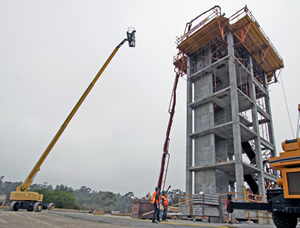
Two graduate students look on as construction crews pour the roof slab on a five-story building at Englekirk Center. The building will be outfitted to test nonstructural components, including a working elevator, stairs, a sprinkler system and medical equipment.

Structural engineers at the UC San Diego Jacobs School of Engineering are preparing for a series of earthquake tests focused on nonstructural components, including a functioning elevator, stairs, ceilings, and passive and active fire suppression systems, such as sprinklers and partition walls, in a full-scale, five-story concrete building on the world’s largest outdoor shake table.

The tests performed at the Englekirk Structural Engineering Center at UC San Diego will be the first of their kind in the United States to focus on a broad range of systems and equipment that can malfunction during an earthquake and make it more difficult to evacuate buildings, which can lead to more injuries and deaths.

Construction crews recently completed the five-story structure with a final pouring of the roof slab. The structure is uniquely outfitted with nonstructural systems that are found in multi-use office and hospital buildings. The top two floors will feature patient beds, a patient lift, computers and other hospital equipment that are common to California medical facilities, including a complete intensive care unit and surgery suite.

“We know very little about the earthquake and post-earthquake fire performance of nonstructural systems in buildings, and even less about those in hospitals,” said Tara Hutchinson, a professor of structural engineering at the Jacobs School and principal investigator for the component of the testing program supported by the National Science Foundation. “Meanwhile, lives and property are being lost due to nonstructural damage, even under moderate seismic events.”

“While building codes in California have attempted to address this by strengthening the requirements for nonstructural components in recent years, components designed to these new requirements have not yet been tested in strong earthquakes,” Hutchinson said. “These tests will help fill this gap in knowledge,” she added.

At 25 ft. by 40 ft., the UC San Diego-Network for Earthquake Engineering Simulation Outdoor Shake Table is the largest shake table in the United States and the largest outdoor shake table in the world. The powerful hydraulic actuators at UC San Diego’s facility can simulate ground motion speeds up to six ft. per second, allowing researchers to create realistic simulations of the most devastating earthquakes on record.
Once construction crews install all non-structural components, engineers will subject the entire five-story building to large simulated earthquakes and fire tests from January through March 2012. Media will be invited to observe key tests during this time and should contact the press office at the Jacobs School of Engineering for updates as the test schedule is developed.

Source: University of California, San Diego

GE, GM in push on EV infrastructure for China

Engineerblogger
Sept 23, 2011

General Electric and General Motors Co. agreed Thursday on a pilot installation of electric vehicle charging stations in Shanghai, the latest step in the automaker's plan to develop infrastructure in China to support sales of its Chevrolet Volt electric car.

As part of the agreement, GE also agreed to buy the extended range electric cars for use at its corporate campus in Shanghai. GM plans to launch the Volt in December in China, where it has made electric vehicles a core part of its strategy for expansion despite doubts Chinese consumers will snap up such cars.

The companies gave no details about investment in the charging stations, which will include both GE's WattStations and Durastations, two different specifications for charging electric vehicles.

China is a linchpin market for GM. Earlier this week it announced plans for developing a new electric vehicle with its local partner Shanghai Automotive Industrial Corp. It also has just opened an advanced technology center to support its efforts to build more energy efficient and safer automobiles, with a lab devoted to developing new battery cells for EVs.

GE builds natural gas-fired generators for utilities, electric motors, advanced electric meters and electric car charging stations, all of which could be in higher demand if drivers buy electric cars. The company estimates the expanding market could bring it up to $500 million in revenue over the next three years.

China, the world's biggest market for new vehicles, is seen as a promising market for electric vehicles because of its keenness on limiting its dependence on costly imports of crude oil and reducing severe pollution from auto emissions.

The government has made development of so-called "new energy" vehicles a key part of its current five-year economic plan, promising subsidies and billions of dollars in new investments.

But spurring demand for electric and hybrid vehicles will hinge on providing the charging infrastructure, and bringing costs down to affordable levels, those working in the industry say.

Thursday's agreement calls for the two big U.S. companies to coordinate work with government agencies on developing EV standards.

In August, GE Energy also announced a partnership with car rental company Hertz Corp. for advancing the rollout of EVs and charging stations in China.

Source:  The Associated Press